Building a Sparrow
For me, there are three aspects to designing starships for Traveller – statistics, deck plans and model. Statistics is probably the most important – how big the ship is, what in-game capabilities it has such as jump range, thrust and weapons. Mongoose Traveller also concentrates heavily on deck plans, though that’s probably the least important from my own perspective since we don’t have combats inside starships too often, so the need for a tactical deck plan hasn’t been a priority.
The third is the model – what does the exterior of the ship actually look like. That’s what I often want to describe to players, and actually drawing something helps fixate that in my head. Whilst doing some designs for a new ship, I got an idea to try and simplify the building of the 3D image. Previously, it’s been a lot of effort building everything from scratch in Blender, and trying to backport that to the deck design.
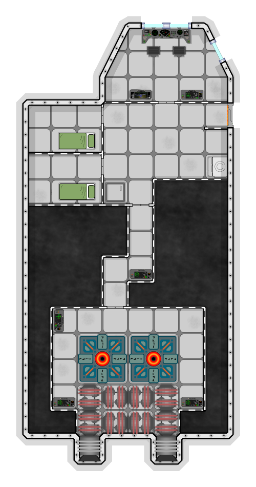
The three aspects are linked. Deck plans use 1.5m x 1.5m squares, and two of them make 1 displacement tonne. So each displacement tonne of jump drive, weapon system or living quarters takes up two squares on the deck plan. Now that I’m using Dungeondraft, it’s not too hard to build the deck plans for a ship, and generate images at 100px per grid square.
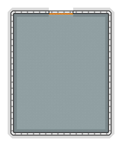
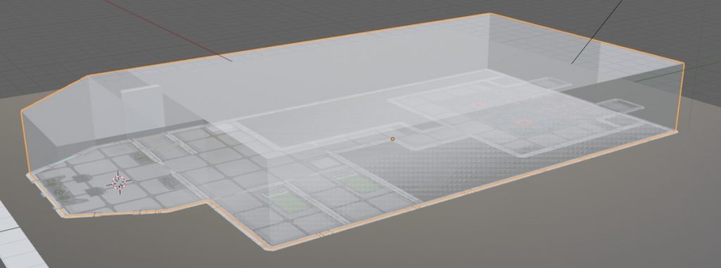
Doing this gave me an idea to aid in the building of the third aspect – I could use the deck plans as the foundation for building a 3D model in blender. Knowing the size of the images, I created a flat plane for each deck of the ship at the right size. In this case, each map was 20×20 tiles, which at 1.5m per tile was a 30m x 30m square plane. Then I dragged in the deckplans and set them as a texture map on each tile.
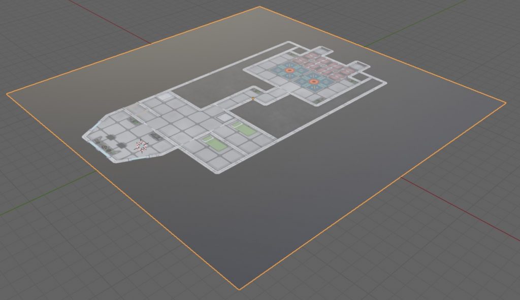
I assumed a 3m height for each deck, so I put deck two 3m above deck 1. This gave me a floor plan of the correct size for the ship, which could then be used as a basis for building from.
With that done, it was just a case of starting to build on top of the texture. I just created a simple box for each deck – the boxes were 2.5m tall (to leave room between decks), but nicely mapped out the interior space needed by the ship. I’m not too bothered by exactly what is in the interior – just the volume that it takes up. Since almost everything was in multiples of 1.5, ensuring that they fitted to the grid wasn’t too hard.
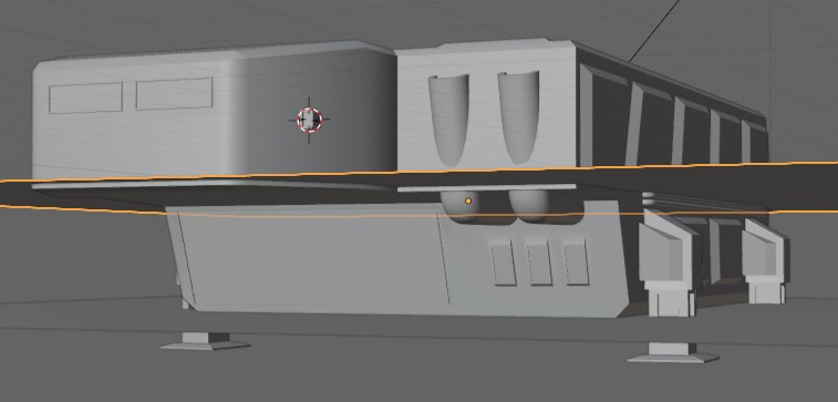
With both decks done, it was then a case of drawing the actual outer hull. This is the bit that actually required some artistic ability, which is why I like to stick to simple block designs.
In theory, the final model should roughly match the size of the original design. It’s going to be slightly larger, since there will be rounded bits of hull that need to stick out, and things such as landing gear and greebles. Any aerodynamic hull should have minimal greebles, but that always looks plain and boring. Fortunately this particular design isn’t aerodynamic.
Once the outer hull is in place, it’s just a case of hiding the deck plans. I could probably fill out interior walls as well if I wanted, but I don’t normally have a need to do that.
For me, the aim is to have a 3D model which as far as possible matches the shape of the deck plans and the volume of the game design. That includes fitting around the height – the wedge shaped 100t scout was particularly hard to do a 3D model for, since the narrow nose doesn’t leave much room for where the bridge is meant to be.
The final design is a slightly asymmetric box design, with a loading bay at the front. Currently the main airlock is up on deck two, which is inconvenient when landed on a planet. There should probably be a second airlock on the cargo deck, but that’s the sort of thing that can be tweaked later.

As far as the game statistics go for the 100t Sparrow, these might appear in an upcoming supplement I’m working on.